Shelfbot Electrical Specification
Doc: SB-SPEC-ELEC
1. Introduction
This document defines the electrical infrastructure for a Shelfbot installation: the circuits, outlets, cabling and compliance obligations required to power the robots, the put-to-light trolleys and the Shelfbot server cabinet. It is written for the customer's licensed electrician, warehouse designers and commissioning technicians preparing a site for Shelfbot deployment.
This specification states what is required; the Customer Site Drawings state where. Every position — outlets, server cabinet, cable drops — is fixed on the Customer Site Drawings, the single authoritative drawing set for the deployment, owned and revision-controlled by Shelfbot. Appendix D of that set is the power and safety device position drawing, carrying the per-row power position schedule (row, robot, outlet position grid reference, circuit ID, drop point).
Per-site completion (circuits, outlet positions, cabling and the certificate of electrical safety) is recorded and verified with Shelfbot during the deployment project. The electrical contractor's contact is provided to Shelfbot at project onboarding. Timing is set by the Shelfbot Project Plan.
2. Related Documents
| Document | Used for |
|---|---|
| Customer Site Drawings — Appendix D | The authoritative positions: every outlet, the server cabinet and each cable drop, with grid references and the per-row power position schedule (safety devices, including each Safety Cabinet with its built-in isolator, are also on the power and safety device position drawing, Grid Design Appendix D) |
| Shelfbot Grid Design | How the positions are designed and confirmed (its Power and Electrical Positions section) |
| Shelfbot Racking Specification | The front-frame double bracing the robot outlets mount on (its Front Frame Requirement section) |
| Shelfbot Project Plan | Programme: when the electrical works must be complete; the site readiness requirement for RCBO outlets |
| Shelfbot Technical Data Sheet | Electrical summary (its Electrical Requirements section) |
3. Electrical Loads
| Load | Circuit | Outlets | Position |
|---|---|---|---|
| Each robot | Dedicated 20A RCBO-protected circuit — not shared | One 20A three-pin industrial switched socket outlet to AS/NZS 3123 (56 Series pattern) plus one standard double 10A GPO | Front-frame double bracing, centred inside the frame (Positions) |
| Put-to-light trolley | Wiring and circuit arrangement per the licensed electrician | One 20A GPO | Ground level, below 700 mm, 1 m in front of robot 1 |
| Server cabinet | Wiring and circuit arrangement per the licensed electrician | One 10A outlet, with the network point | At the server cabinet position on the Customer Site Drawings |
- Supply: 240 V AC ±10%, 50–60 Hz
- Robot current: approximately 2 A idle, up to approximately 18 A operational
- Circuit protection: user-supplied 20A residual current circuit breaker with overload protection (RCBO) — required on every robot circuit
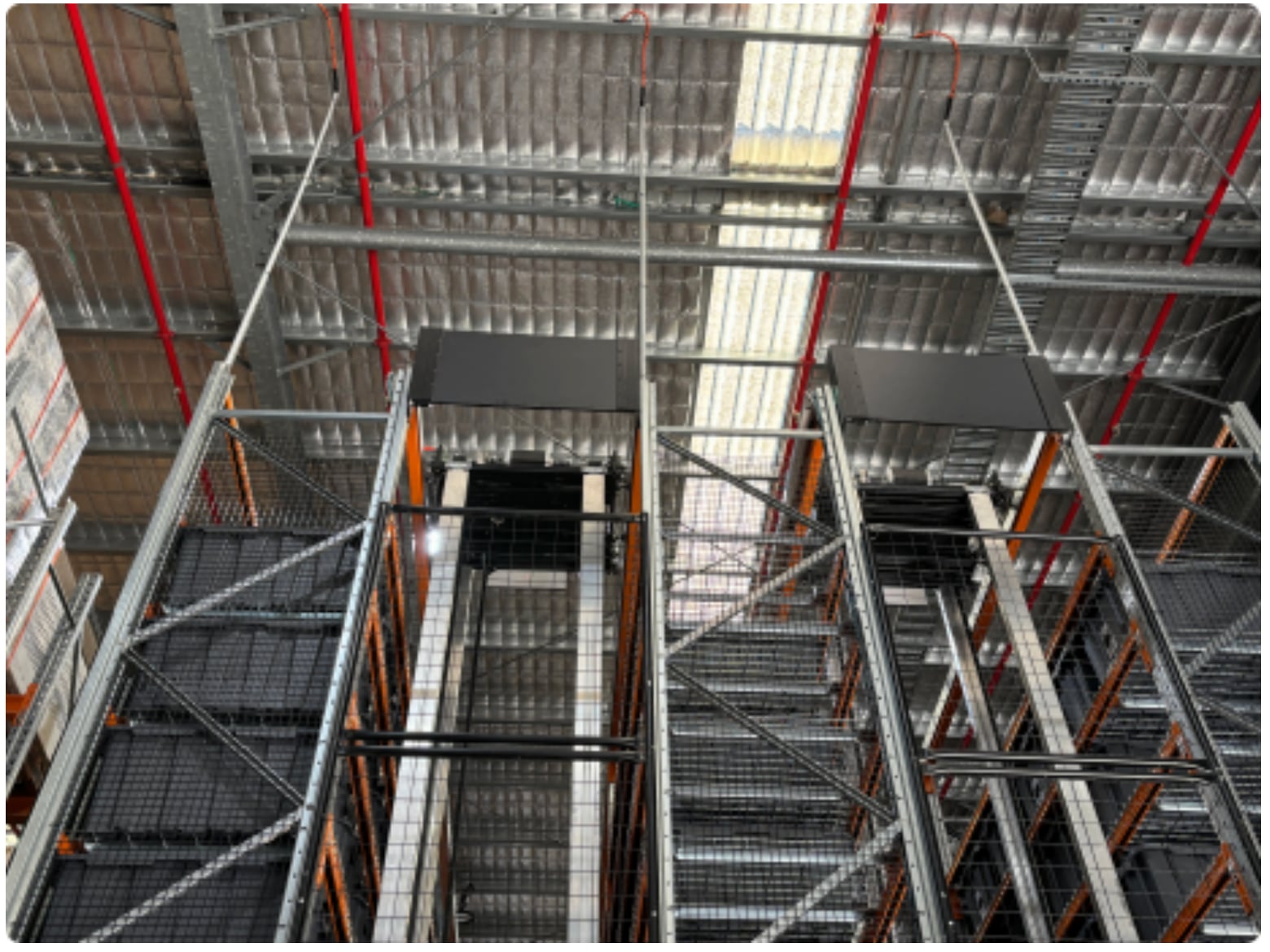
Figure: Example installation with three rows of racking and two Shelfbots
4. Positions
No outlet or cable drop is positioned from this document alone — every position is placed on the power and safety device position drawing of the Customer Site Drawings (Appendix D) with a grid reference, and installation to any other position is a deviation requiring Shelfbot's written approval before works.
- Robot outlets — mounted on the racking front-frame double horizontal bracing, centred on the inside of the frame. The bracing is specified in the Racking Specification under Front Frame Requirement; the upper brace sits no higher than 350 mm above ground, or the electrical cabinet will not fit within the frame footprint.
- Put-to-light trolley GPO — at ground level, mounted at a height of less than 700 mm, positioned 1 m in front of robot 1.
- Server cabinet — power and network point at the cabinet position fixed in the Grid Design and shown on the drawings.
Isolation. Each robot's supply is isolated at its switched 20A outlet. The system isolation and lockout/tagout (LOTO) point is the isolator built into the Shelfbot Safety Cabinet — Shelfbot-supplied equipment, positioned on the drawings with the safety devices; it is not part of the electrician's supply. The Safety Cabinet connects to the robot's outlet by its supplied lead and plug — there is no fixed wiring to the Shelfbot system, and no electrician attendance is required for connection or disconnection; Shelfbot plugs in at commissioning.
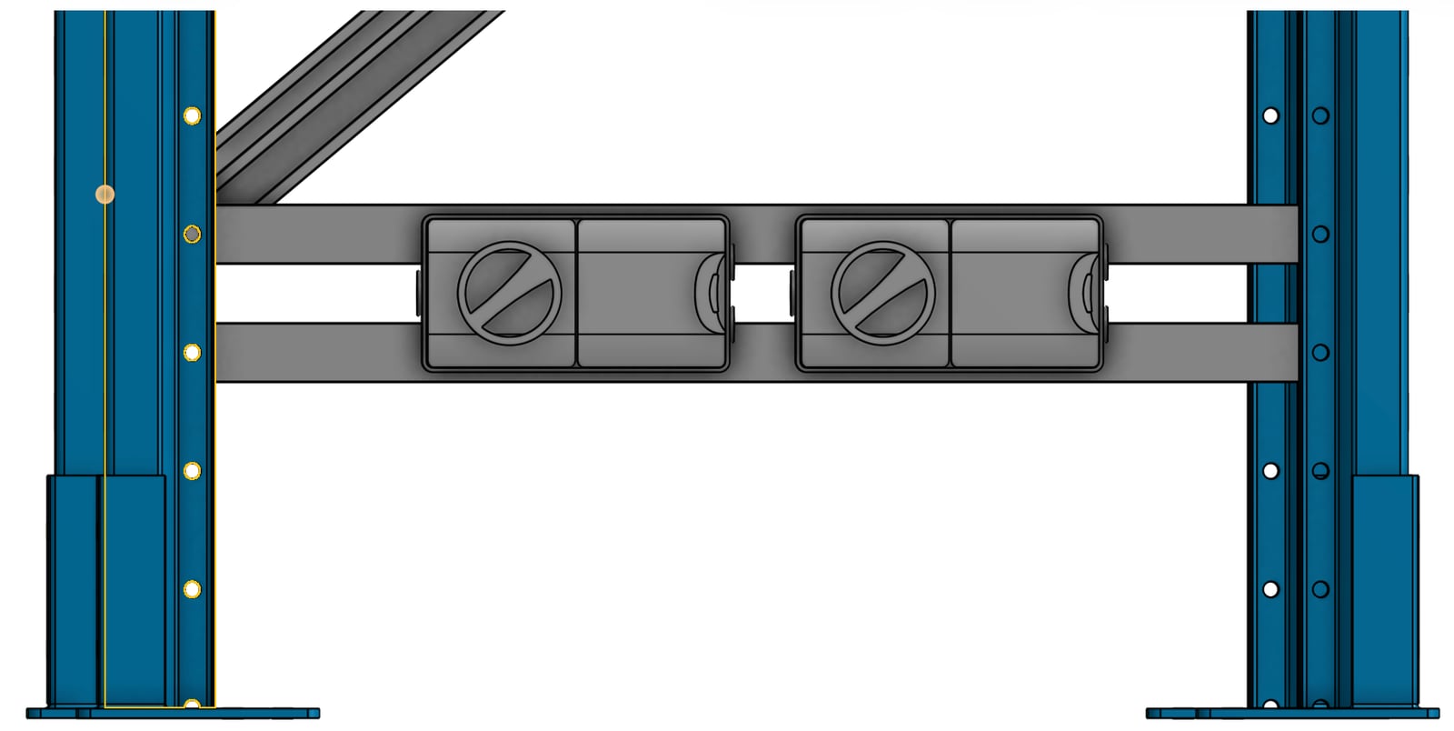
Figure: Power outlets mounted on the racking horizontal bracing at the front of the row
5. Cabling & Conduit
Each robot circuit:
- A dedicated 20A RCBO-protected circuit feeding the 20A outlet and the double 10A GPO — not shared with other equipment
- Cable routed from the ceiling down the LEFT side of the racking upright, left as viewed facing the racking from the front, at the drop points on the Customer Site Drawings
- 20 mm rigid conduit installed INSIDE the racking upright profile. The conduit must sit fully within the upright so it cannot interfere with the robot sensors or with tote extraction; conduit mounted on the aisle face of the upright is not acceptable
- Minimum 4 mm² 3-core cable. Final size is determined by the licensed electrician per AS/NZS 3000 and AS/NZS 3008 for the actual run: current-carrying capacity in conduit, grouping with other robot circuits, ambient temperature, and voltage drop over the route length (long runs typically require 6 mm²)
Cable routing must not interfere with:
- Sprinkler lines
- Racking structural elements
- Shelfbot safety guarding
- The robot travel path
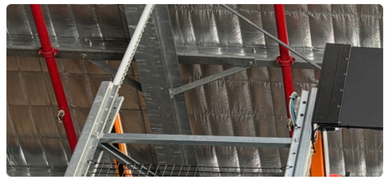
Figure: Cable drop from ceiling; conduit installed inside the racking upright
6. Compliance & Certification
All electrical works are performed by a licensed electrician engaged by the Customer.
All cabling and installation comply with AS/NZS 3000 (Australian Wiring Rules).
The source switchboard and spare ways are confirmed before works commence; every circuit is labelled with its circuit ID from the power position schedule on the Customer Site Drawings.
A permanent warning sign is fitted at the source switchboard, at or beside the Shelfbot circuit group, reading:
SHELFBOT ROBOT SYSTEM These circuits supply the Shelfbot Robot System. DO NOT SWITCH OFF without Shelfbot authorisation, except in an emergency. Unauthorised isolation stops live order fulfilment. Shelfbot: +61 3 9069 5000
The Shelfbot circuit IDs are grouped and identified so the sign unambiguously covers all of them.
On completion, a certificate of electrical safety is provided to Shelfbot as evidence that the electrical works are complete. The electrician's works end there: the Shelfbot system connects to the outlets by plug, so no electrician attendance is required during installation or commissioning.
7. Revision History
| Version | Date | Change |
|---|---|---|
| 3.1 | 19/08/2026 | Published to Web Site |
| 3.2 | 24/08/2026 | Robot outlet specified as 20A to AS/NZS 3123 56 Series pattern plus a standard double 10A GPO; switchboard warning sign required |