Shelfbot Racking Specification
Doc: SB-SPEC-RACK
1. Introduction
This document defines the racking requirements for a Shelfbot Automated Storage & Retrieval System (ASRS) installation. It is intended for warehouse designers, racking suppliers, installers, and commissioning technicians responsible for preparing a site for Shelfbot deployment.
The racking system forms a structural component of the Shelfbot solution and must be designed, supplied, and installed in accordance with this specification.
2. Purpose & Scope
2.1 Purpose
The purpose of this specification is to define the minimum racking infrastructure requirements necessary to safely and reliably operate the Shelfbot ASRS, including structural interfaces required for robot rails, tote storage, and electrical equipment mounting.
2.2 Scope
This document covers:
- Pallet racking type and compliance requirements
- Beam types and configurations
- Frame dimensions and pitch
- Mesh decking requirements
- Base plate constraints
- Aisle and clearance requirements
- Installation notes specific to Shelfbot interfaces
This document does not cover:
- Robot mechanical or electrical specifications
- Control systems, software, or networking
- Warehouse fire engineering or sprinkler design for the fire protection design parameters of the Shelfbot system (tote construction, flue spaces, clearances, sprinkler design basis), refer to the Shelfbot Fire Protection document
- Floor slab design or certification
For these topics, refer to the Shelfbot User Manual and relevant Shelfbot technical specifications.
3. Racking Overview
- Shelfbot robots are installed on steel pallet racking compliant with AS4084:2023.
- Each Shelfbot shelf typically stores five (5) totes uniformly spaced across the bay.
- Maximum tote weight (including contents): 30 kg
- Maximum shelf load: 150 kg UDL
- Shelfbot systems may be configured in single-row or double-row racking layouts, depending on site design.
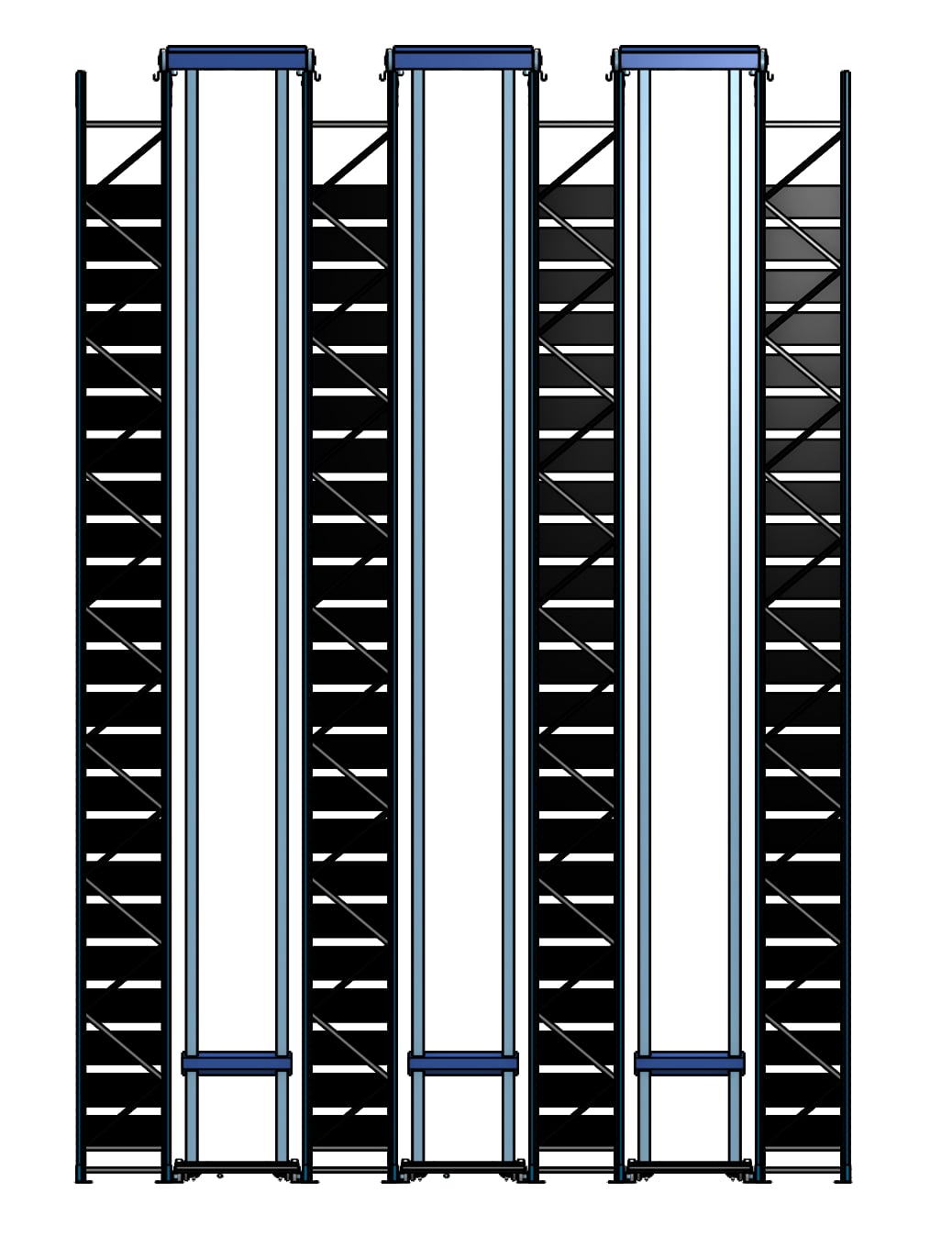
Figure: Three Bots on Single Rows
4. Parts & Hardware
4.1 Beams (General)
- Box or drop (step) beams are acceptable
- Beam face heights: 40 mm to 100 mm (50mm recommended)
- Open or closed section beams permitted
- All beams within a row must be the same height, tolerance ±1 mm
- All beams shall be load-rated and certified by the racking supplier to exceed the maximum Shelfbot shelf load, including dynamic and automation factors, in accordance with AS4084.
4.2 Frames (Uprights)
- Height range: 4 m to 10 m
- Frame depth: 838 mm
- Upright pitch options:
- 50 mm
- 75 mm
- 76.2 mm (3")
- Racking to be installed plumb and square in accordance with AS4084 tolerances.
4.3 Bottom Beam
The bottom beam should be installed as low as practical to maximise grid density, with a required minimum of ~300 mm above floor level.
- Standard beam typically 50 mm
- Installed height: ~300 mm minimum above floor level
4.4 Top Rail
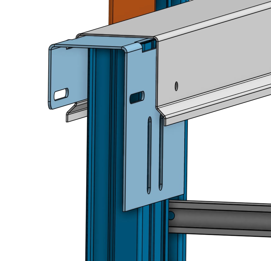
- Shelfbot will provide a roll-formed custom top rail that sits flush with the top of the upright and acts as a rail for the robots.
- Each top rail is fitted with a rack upright cap mounted to the top of the racking uprights. Cap dimensions: 200 mm long × 80 mm deep × 200 mm high. Rack upright caps are fabricated and supplied by Shelfbot.
- Each upright-top assembly requires six bolts with mudguard washers, all to the same specification as the base-plate fixings, supplied and fitted by the racking company during installation (the same bolts it already uses for the base plates): two securing the rack upright cap to the upright, and four securing the top rail to the cap.
- The pair of parallel bolt holes (coffin slots) in the upright face must be unobstructed at a height between 50 mm and 100 mm below the top of the upright — one cap fixing through each.
- Rails and caps will be shipped directly to the racking company or client installation site.
- The preferred arrangement is for the racking company to install the top rails and caps, subject to capability and written agreement between the client, the racking company, and Shelfbot; otherwise Shelfbot will perform the installation (see Notes & Responsibilities).
- Shelfbot will provide installation instructions for these rails.
Top rail profile and rack upright cap detail
4.5 Bottom Rail (Robot Bottom Rail)
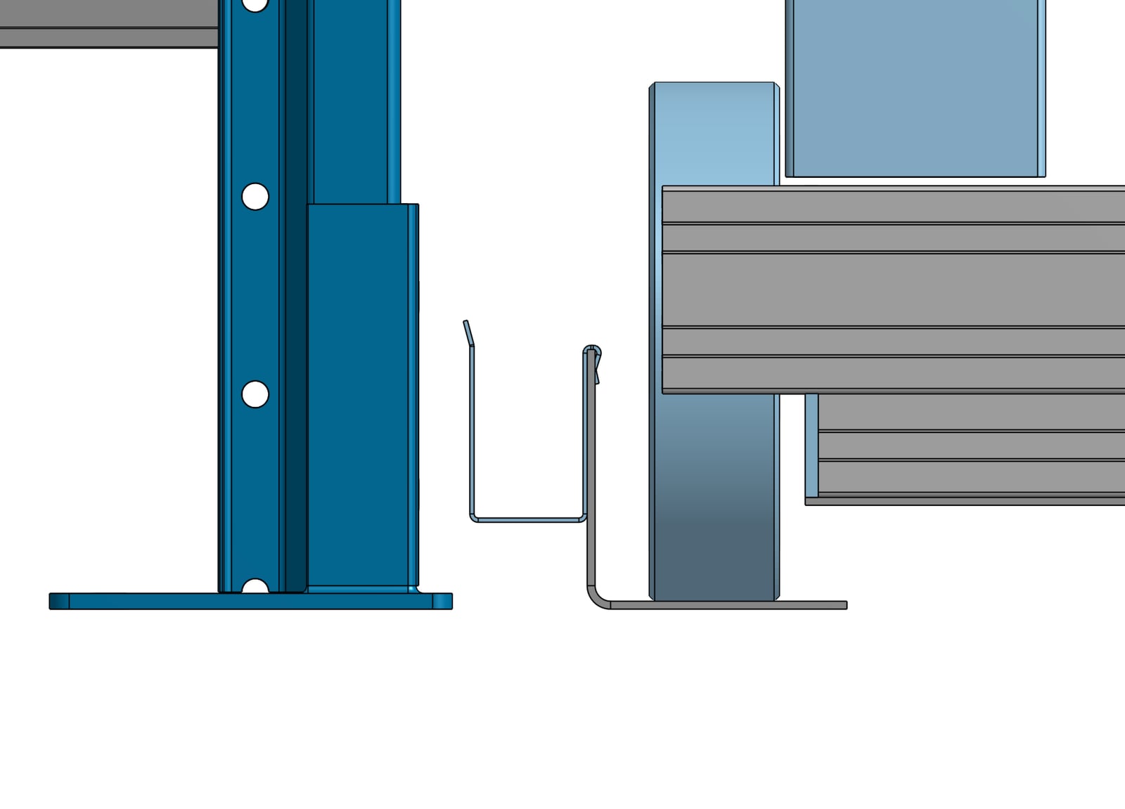
- Shelfbot will provide a roll-formed steel bottom rail that is screw-fixed to the concrete slab.
- The robot drag chain is housed within the bottom rail profile.
- Bottom rails are installed at a clear outside-to-outside spacing of 1050 mm to provide room for the drag chain channel as shown below. The spacing is also designed to fit a narrow-aisle scissor lift up to 810 mm wide, allowing it to drive down the aisle between the bottom rails for installation and maintenance access.
- Rails are fabricated and supplied by Shelfbot.
- The preferred arrangement is for the racking company to install the bottom rails, subject to capability and written agreement between the client, the racking company, and Shelfbot; otherwise Shelfbot will perform the installation (see Notes & Responsibilities).
Bottom rail profile
4.6 Mesh Decks
- Standard waterfall wire mesh decking
- Typical size: 1250 mm × 838 mm
- Typically 2 mesh decks per shelf
- Recommended 4 support channels, 1.8 mm thick
- Wire diameter: 5 mm nominal (min 4 mm, max 6 mm)
- Aperture: 100 × 50 mm
- Maximum depth: 860 mm
- Maximum mesh UDL: 1000 kg
Mesh decks must be rated and certified to suit the beam span and loading.
Note
The specified mesh geometry provides a uniformly open area of not less than 70% (nominally 84–89% across the permitted wire diameter range). This is a fire protection requirement - solid shelves or decking with less than 70% open area must not be substituted. Refer to the Shelfbot Fire Protection document.
4.7 Base Plates
- Maximum projection: 50 mm beyond upright profile
- Plates to be:
- Mechanically anchored to concrete
- Shimmed as required for levelling
- Suitable for automated system loads
Extended or seismic-style base plates are not permitted unless approved by Shelfbot.
4.8 Back-of-Rack Guarding (Outer Rows)
Outer racking rows must be fitted with a backing system (e.g., Manta Mesh Backing System) with 225 mm brackets installed to a minimum height of 2.5m. The remaining height of the outer racking rows must have wire mesh 50mm x 50mm or 100mm x 100mm installed to the full height of the installed racking.
5. Installation Requirements
5.1 Aisle Width & Row Spacing
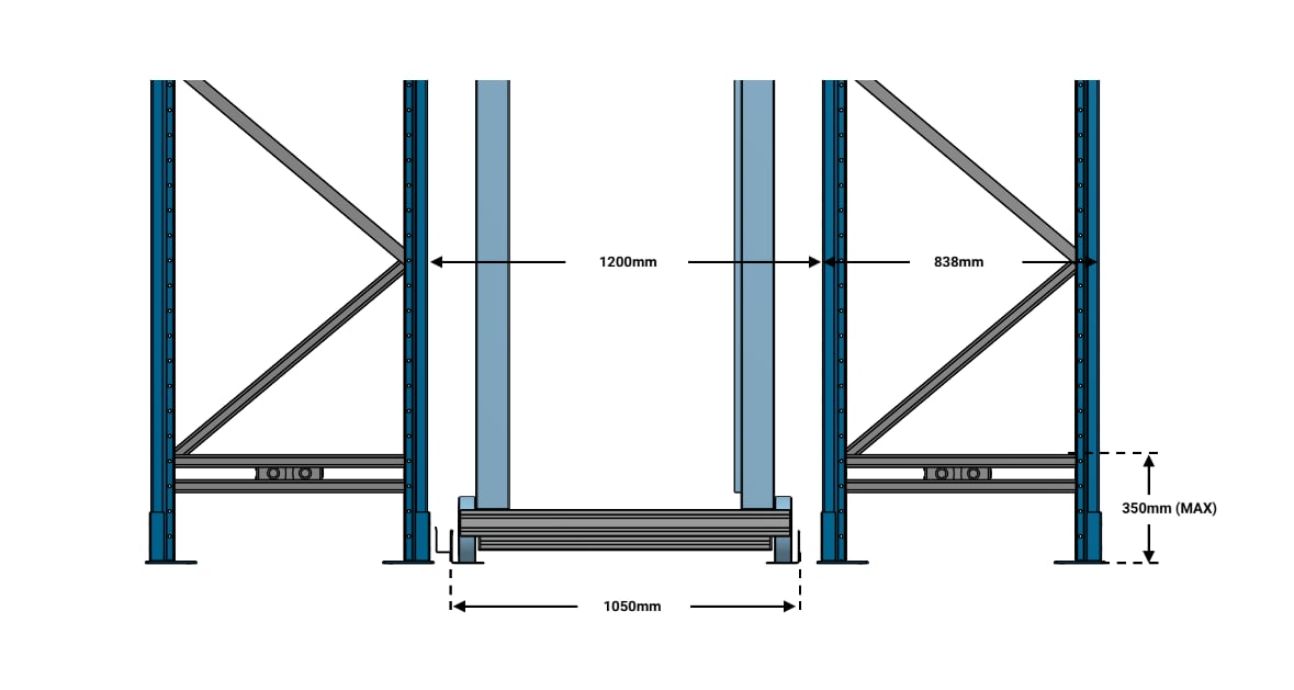
- Aisle width: 1200 mm upright-to-upright. Shelfbot operating envelope and rail clearances are designed relative to this nominal dimension. Minor variation due to installation tolerances is acceptable provided minimum clearances are maintained.
- Bottom rails are installed at a minimum clear outside-to-outside distance of 1050 mm. This spacing provides room for the drag chain housed within the bottom rail profile, and is designed to fit a narrow-aisle scissor lift up to 810 mm wide driving down the aisle between the bottom rails for installation and maintenance access.
- A minimum 3 m clear zone must be maintained at both the front and rear of the grid to provide scissor lift access.
- Bollard requirements (locations, type, supply, and installation) are to be discussed and agreed between the racking supplier and the customer.
- No racking components may encroach into the Shelfbot operating envelope.
- Double-row layouts: a minimum 150 mm clear longitudinal flue space must be maintained between back-to-back rows, kept free of obstructions for the full height of the racking (fire protection requirement - refer to the Shelfbot Fire Protection document).
5.2 Vertical Spacing
Shelfbot operates only with Shelfbot-supplied totes. The standard tote is 820 mm long × 420 mm wide; length may range from 700 mm to 950 mm and height from 150 mm to 350 mm by customer requirement. Width is fixed at 420 mm.
The loaded tote must sit fully within the rack footprint and must not protrude into the aisle.
Vertical pitch must provide a minimum 40 mm clearance between the top of the tote and the underside of the beam above, for tote handling and robot tolerances.
5.3 Base Plate
Plate to be anchor-fixed to concrete and shimmed as required. Suitable for automated system loads. Maximum 50 mm beyond upright profile.
5.4 Front Frame Requirement
The front of each row is the end where the Operator Station is located - the point at which operators access presented totes through the Roller Door.
For the first frame in each row:
- Two horizontal braces must be installed at the bottom of the front frame with a centre-to-centre vertical separation of 100 mm (min) to 200 mm (max).
- The upper horizontal brace must be a maximum of 350 mm above ground level.
This configuration allows for installation of industrial electrical outlets mounted on the two horizontal braces, centred on the inside of the frame.
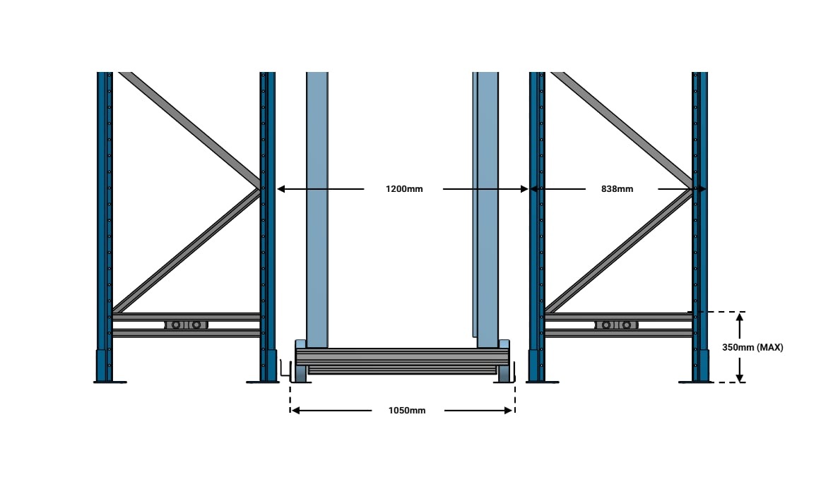
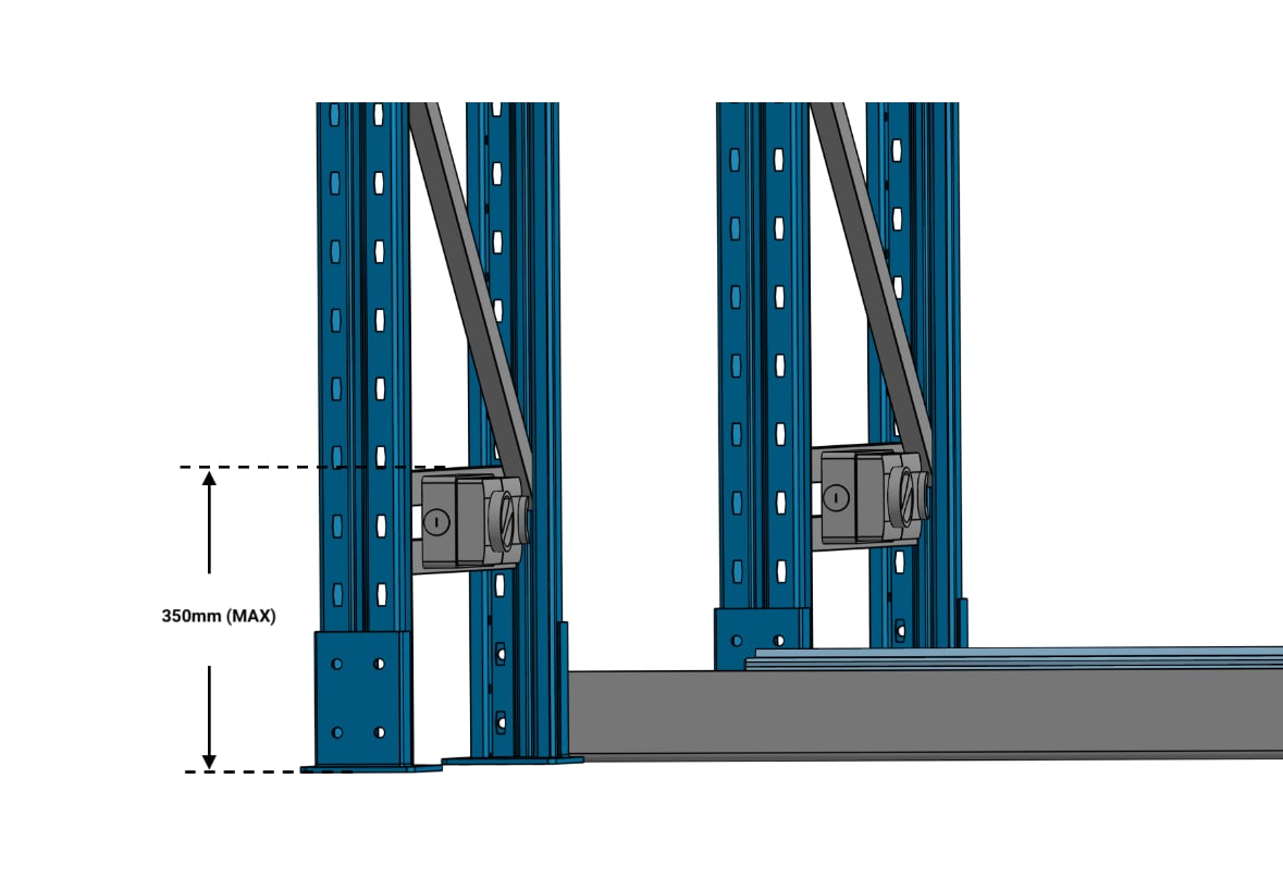
Figure: Double Bracing
Note
The two horizontal braces at the bottom of the first frame no higher than 350 mm. Failure to do so will prevent fitment of the electrical cabinet within the frame footprint.
6. Notes & Responsibilities
6.1 Responsibility Matrix
The table below records who supplies and who installs each element of the racking scope. Where an item shows Racking supplier*, the preferred arrangement is for the racking supplier to perform the work where they have the capability, subject to written agreement between the Customer, the racking supplier, and Shelfbot; in the absence of such agreement, Shelfbot performs the work. The agreed party for each site is recorded in writing.
| # | Item | Supplied by | Installed by |
|---|---|---|---|
| 1 | Pallet racking (frames, beams, bracing) | Racking supplier | Racking supplier |
| 2 | Structural certification to AS4084 | Racking supplier | — |
| 3 | Load signage (aisle entry points, per AS4084) | Racking supplier | Racking supplier |
| 4 | Mesh decks (Mesh Decks) | Racking supplier | Racking supplier |
| 5 | Base plates and anchors, selection and installation (Base Plates) | Racking supplier | Racking supplier |
| 6 | Back-of-rack guarding, outer rows (Back-of-Rack Guarding (Outer Rows)) | Racking supplier | Racking supplier* |
| 7 | Top rails (Top Rail) | Shelfbot | Racking supplier* |
| 8 | Rack upright caps (Top Rail) | Shelfbot | Racking supplier* |
| 9 | Bottom rails, screw-fixed to slab (Bottom Rail (Robot Bottom Rail)) | Shelfbot | Racking supplier* |
| 10 | Drag chain, housed in bottom rail (Bottom Rail (Robot Bottom Rail)) | Shelfbot | Shelfbot |
| 11 | Bollards (Aisle Width & Row Spacing) | As agreed between racking supplier and Customer | As agreed between racking supplier and Customer |
| 12 | Electrical outlets on front frame (Front Frame Requirement, per Electrical Specification) | Customer (licensed electrician) | Customer (licensed electrician) |
| 13 | Robots, robot installation and commissioning | Shelfbot | Shelfbot |
| 14 | Racking shop drawings (manufacturing detail), checked against the Shelfbot Customer Site Drawings and issued for three-party sign-off before manufacture. The Customer Site Drawings are the single authoritative drawing set, owned by Shelfbot — the supplier does not issue layout drawings | Racking supplier | — |
* Racking supplier preferred where capable, subject to written three-party agreement; otherwise Shelfbot.
Any deviation from this specification must be approved in writing by Shelfbot prior to manufacture or installation.
Per-site agreed values (layout, dimensions, installation parties, bollard arrangements) are recorded per project, not in this specification.
7. Revision History
| Version | Date | Change |
|---|---|---|
| 3.1 | 19/08/2026 | Published to Web Site |